24-hour hotline:+8613662168047
Keyword search: battery plant , lithium battery factory , power bank works , lifepo4 battery mill , Pallet Trucks LiFePO4 Battery, LiFePO4 Pallet Trucks Battery, Lithium Pallet Trucks Battery,
Silicon, as a future negative electrode material, has a theoretical capacity of about 4200mAh/g, which is more than 10 times higher than the 372mAh/g of graphite negative electrodes. After industrialization, it will greatly enhance the capacity of batteries. However, the main problems with silicon materials now are: 1. During charging and discharging, the volume expands by 300% -400%; 2. High irreversible capacity and low coulombic efficiency result in actual capacity loss and poor cycle life. After alloying with lithium, there is a significant change in the volume of silicon crystals, which can easily cause the silicon negative electrode material to pulverize and peel off from the current collector due to the volume effect. Moreover, the peeling caused by the volume effect of silicon can lead to repeated damage and reconstruction of SEI, thereby increasing the consumption of lithium ions and ultimately affecting the capacity of the battery. We are currently solving the above problems through methods such as silicon powder nanomaterialization, silicon carbon coating, doping, and adhesive optimization.
From an engineering perspective, in order to improve the energy density of the battery, it is necessary to control the total mass of the electrode or battery, which includes the active material, liquid electrolyte filled in the electrode pores, binders and conductive additives, and current collectors. Therefore, the energy density of the electrode depends on the mass ratio of the active material to the inactive material used. The common techniques for improving the energy density of porous electrodes include increasing electrode thickness (ratio of active material/current collector) and reducing porosity (ratio of electrolyte/active material). However, due to the limitations of lithium ion transport within the electrode, an increase in electrode thickness and a decrease in porosity will reduce the power density of the battery. In addition, the proportion mixed with graphite negative electrode will affect the capacity and average volume expansion of the composite electrode. Therefore, optimizing these design parameters is the key to developing high-energy and high-power lithium-ion batteries.
Heubner et al. considered the mixing ratio of silicon and graphite, the volume expansion of the material, and determined the optimization design criteria for silicon-based porous electrodes. They defined the "deformation threshold", which means that due to the volume expansion of the silicon negative electrode, the original pores in the electrode will be filled and the porosity will be reduced. In order to avoid severe deformation and stress caused by electrode particle contact during charging, as well as a sharp decrease in porosity, the initial porosity of the electrode has a minimum value. When designing electrodes, the porosity must be greater than this value. In addition, a "rate current threshold" is defined to ensure that the diffusion limited current is not lower than the required rate current, thereby avoiding a significant reduction in capacity during fast charging. Further analyzed the impact of these design criteria on the performance parameters of silicon-based negative electrodes, and optimized the electrode design parameters using the derived criteria relationship to ensure electrode energy density and power density.
1. Porosity rate
The porosity ε 0 of lithium-ion battery electrodes can be expressed by equation (1):
(1) Vi is the volume of each solid phase component in the electrode, including silicon (Si), graphite (C), binder (B), and conductive agent (A). V is the overall volume of the electrode coating. Assuming SOC=0 and SOC=1, the volume change of each solid phase component is linear, and the expansion volume of each phase is ni times the initial value. (The volume expansion of silicon, graphite, conductive agent, and binder is nSi=3, respectively.), nC=0.1,nA=0,nB=0), When considering this volume expansion, the electrode porosity ε (SOC) under different SOC states is given by equation (2):
(2) Assuming that the overall expansion of the battery is limited to ns times (such as 10%) by the outer packaging shell, the true density ρ i of each solid phase (the densities of silicon, graphite, conductive agent, binder, and electrolyte are ρ Si=2336, ρ C=2200, ρ A=2200, ρ B=1800, ρ CC=8920, ρ el=1500, respectively) and the mass percentage ω i are taken into account to obtain equation (3):
(3) According to formula (3), for electrodes with different initial porosities, the relationship between electrode porosity and SOC during lithiation is shown in Figure 1a, and Figure 1b is a schematic diagram of the corresponding microstructural changes (assuming that the overall expansion of the electrode is limited to ns=10%). With the increase of SOC, the porosity decreases significantly. When the initial porosity is within the range of 20-40% (typical porosity of commercial graphite electrodes), the porosity of silicon-based electrodes will rapidly decrease to zero during charging. This process can cause significant mechanical stress inside the electrode, leading to silicon fragmentation, electrical contact failure, and capacity degradation. In the case of moderate initial porosity (50-70%), the decrease in porosity is not as significant. However, in order to maintain SOC=1 and prevent the electrode porosity from decreasing to 0, the initial porosity needs to be above 80%.
Figure 2a shows the relationship between porosity and initial porosity under SOC=1 lithiation state of electrodes with different silicon contents. Increasing silicon content leads to denser electrodes after lithiation. For pure graphite electrodes, the volume expansion of graphite is 10%. If the electrode volume change is limited to 10%, the porosity remains unchanged after lithiation. Figure 2b shows the relationship between porosity and initial porosity at SOC=1 lithiation state for three different silicon content electrodes under different limits of electrode overall volume change (0%, 10%, 20%). The smaller the limit of electrode overall volume change, the smaller the decrease in electrode porosity after lithiation.
2. Li distribution in electrolyte
In lithiation reaction, lithium ions are inserted into the active material from the electrolyte, and the lithium concentration in the electrolyte decreases in the pores of the electrode. A concentration gradient is formed across the entire electrode, causing lithium to diffuse towards the negative electrode. If the lithium concentration in the electrolyte drops to zero, the lithium insertion reaction stops. Therefore, the maximum achievable current, also known as the limit diffusion current jlim, can be expressed as equation (4), and the effective diffusion coefficient is related to the porosity.
(4) Figure 3 is a schematic diagram of the lithium concentration distribution in the electrolyte during constant current charging at different porosities. (a) Under high porosity, the transport of lithium in the electrode is sufficient to bring the lithium concentration in the electrolyte close to the initial value. (b) By reducing porosity, the concentration of lithium ions in the electrolyte gradually decreases, forming a concentration gradient. (c) Continuing to reduce the porosity, the lithium concentration inside the electrode approaches zero. (d) At very low porosity, the lithium concentration in the entire electrode rapidly decreases to zero.
Figure 4 shows the evolution process of diffusion limit current rate during lithiation under different initial porosities. As SOC increases, the rate performance decreases. For example, at an initial porosity of ε 0=80%, the maximum diffusion limited current of the electrode at SOC=0 is 9.6C, while SOC=1 is approximately 0.85C.
Figure 5 shows the relationship between diffusion limiting rate and initial porosity under different electrode thicknesses and silicon contents. As the initial porosity increases, the rate performance improves. At a certain initial porosity, the diffusion limited current decreases with increasing electrode thickness. Electrodes that are particularly thick or have extremely small pores are usually limited by diffusion, and the maximum charge discharge rate sharply decreases at SOC=1. In addition, increasing the graphite content in composite materials can significantly improve the rate performance of electrodes.

Lithium Batteries ,Ensure Quality
Our lithium battery production line has a complete and scientific quality management system
Ensure the product quality of lithium batteries
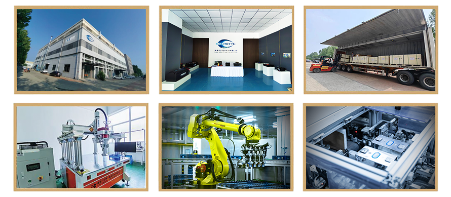
Years of experience in producing lithium batteries
Focus on the production of lithium batteries
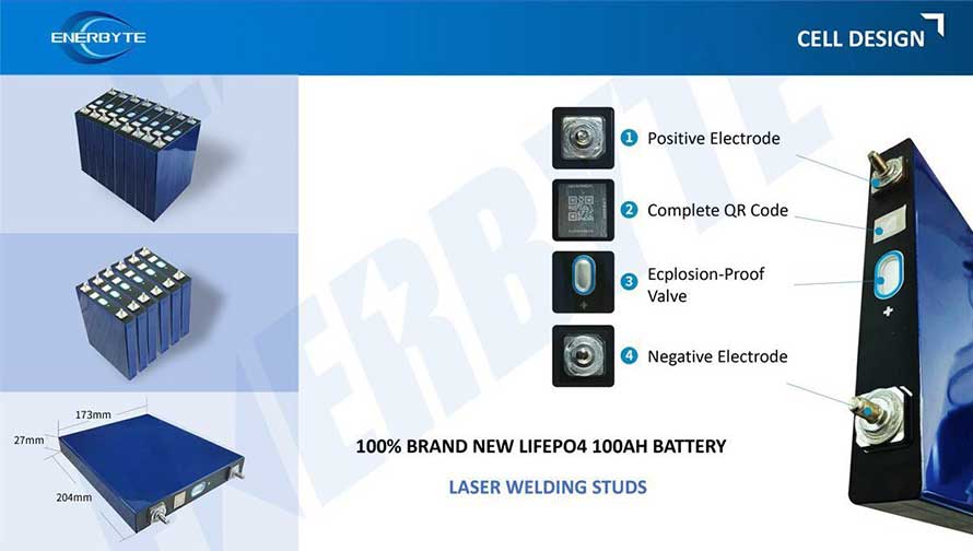
WE PROMISE TO MAKE EVERY LITHIUM BATTERY WELL
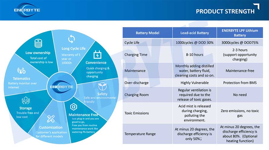
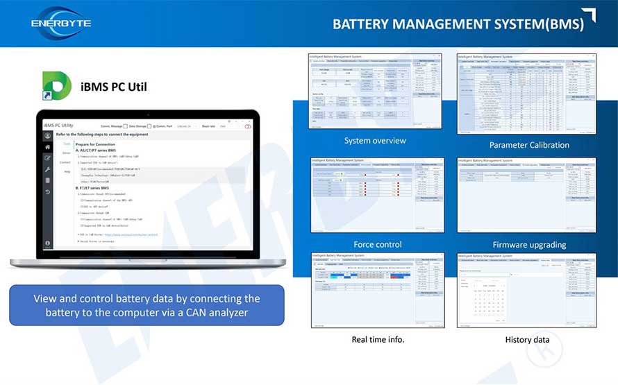
We have a comprehensive explanation of lithium batteries
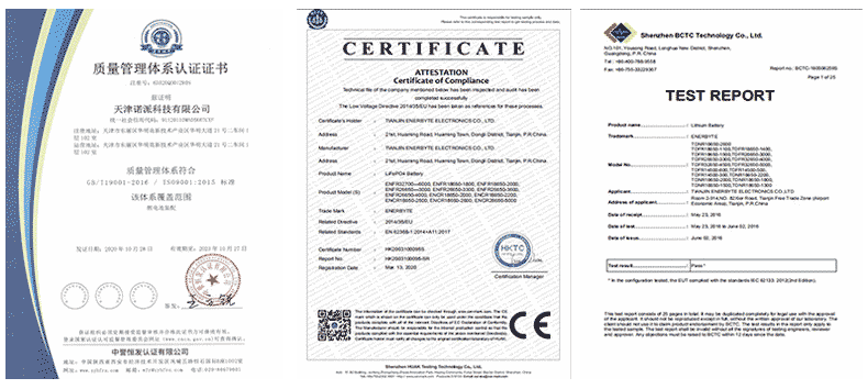
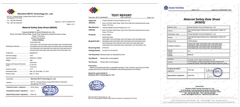
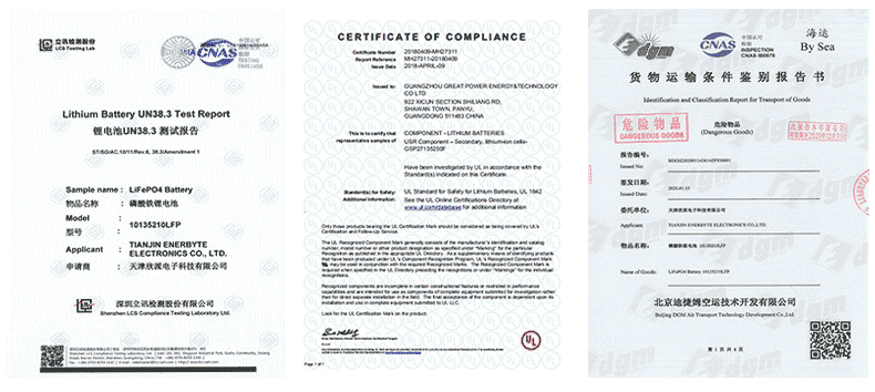
QUALIFICATION CERTIFICATE
THE QUALITY OF COMPLIANCE PROVIDES GUARANTEE FOR CUSTOMERS
MULTIPLE QUALIFICATION CERTIFICATES TO ENSURE STABLE PRODUCT QUALITY
Providing customers with professional and assured products is the guarantee of our continuous progress.

Applicable brands of our products


 Service hotline