24-hour hotline:+8613662168047
Keyword search: battery plant , lithium battery factory , power bank works , lifepo4 battery mill , Pallet Trucks LiFePO4 Battery, LiFePO4 Pallet Trucks Battery, Lithium Pallet Trucks Battery,
1: Lithium battery type and capacity selection.
Firstly, the continuous current that the battery needs to provide should be calculated based on its own motor power (actual power is required, and the riding speed usually corresponds to a corresponding actual power). For example, if the motor has a continuous current of 20A (1000W motor at 48V), then the battery needs to be able to provide 20A current for a long time with low temperature rise (even if the temperature outside is 35 degrees Celsius in summer, it is best to control the battery temperature below 50 degrees Celsius). In addition, if the current is 20a at 48v and the overpressure is doubled (96v, such as in ECPU3 gear), the current will continue to be around 50a. If you prefer long-term overpressure use, please choose a battery that can continuously provide 50a current (still pay attention to temperature rise issues). The continuous current of the battery here is not the manufacturer's nominal battery discharge capacity. The merchant's nominal discharge capacity is several C (or tens or hundreds of amperes), but if discharged at this current, the battery will generate serious heat. If heat dissipation is not done well, the battery life will be very short. (And our electric vehicles use battery environments where batteries are piled up and discharged, leaving almost no gaps. The packaging is very tight, let alone how to do a good job of forced air cooling and heat dissipation.). Our usage environment is very harsh. The discharge current of the battery needs to be reduced for use. Evaluating the discharge current capability of a battery is to determine the corresponding temperature rise of the battery at this current.
The only principle discussed here is actually the temperature rise of the battery during use (high temperature is the enemy of lithium battery life). It is best to control the battery temperature below 50 degrees. (The best temperature range is between 20-30 degrees). This also means that if it is a capacity type lithium battery (controlled to discharge below 0.5C), providing a continuous discharge current of 20a requires a capacity of more than 40ah (of course, the most important factor is the internal resistance of the battery). If it is a power type lithium battery, it is normal to discharge continuously at 1C. Even for A123 ultra-low internal resistance lithium-ion batteries, it is best to discharge at 1C (not exceeding 2C is better, 2C discharge can only run out of battery after half an hour, and it has little practical value). The selection of capacity depends on factors such as the size of the car's storage space, personal expenditure budget, and the expected range of car activities. (Small capacity generally requires power type lithium batteries)
2: Selection and assembly of batteries
The biggest taboo of using lithium batteries in series is that the battery self discharge is severely unbalanced. As long as everyone is equally unbalanced, it doesn't matter. The problem is that this state is urgent and unstable. Good batteries have very little self discharge, while bad batteries have a lot of self discharge. The state of self discharge that is not small usually changes from good to bad, and this process is unstable. So it is necessary to screen out batteries with high self discharge, and only leave batteries with low self discharge for matching (generally qualified products have small self discharge, and the manufacturer has measured it, the problem is that many unqualified products enter the market).
On the basis of small self discharge, select series connections with similar capacities. Even if the capacity is not similar, it will not affect the battery life, but it will affect the usable capacity of the entire set of batteries. For example, if 15 batteries have a capacity of 20ah and only 1 battery has a capacity of 18ah, then the total capacity of this set of batteries can only be 18ah. In the end, the battery will run out of battery, and the protection board needs to protect it. The voltage of the entire set of batteries is still relatively high (because the other 15 batteries have normal voltage and still have electricity). So the high or low discharge protection voltage of the entire set of batteries can indicate whether the capacity of the entire set of batteries is consistent (provided that each cell is fully charged when the entire set of batteries is fully charged). In short, the uneven capacity does not affect the battery life, but only the overall capacity of the group, so try to choose assemblies with similar capacities.
The assembly of batteries must ensure good Ohmic contact resistance between the electrodes. The smaller the contact resistance between the wire and the electrode, the better. Otherwise, if the contact resistance is high, the electrode will generate heat, which will be transferred to the interior of the battery cell along the electrode and affect the battery life. Of course, the manifestation of high assembly resistance is the large voltage drop of the battery pack under the same discharge current. (The voltage drop is partly due to the internal resistance of the battery cell, and partly due to the assembled contact resistance and wire resistance)
3: Selection and charging and discharging instructions for the protective version (data for lithium iron phosphate batteries, the principle of a regular 3.7V battery is the same, but the data is different)
The purpose of the protection board is to protect the battery from overcharging and over discharging, prevent high current from damaging the battery, and perform battery voltage balancing when fully charged (the balancing ability is generally small, so it is difficult to balance with a high self discharging battery cell protection board, and there are also protection boards that are balanced in any state, that is, balancing is done from the beginning of charging, which seems rare).
For the lifespan of the battery pack, it is recommended that the charging voltage of the battery should not exceed 3.6V at any time, which means that the protective board protection action voltage should not exceed 3.6V. The recommended balanced voltage is 3.4V-3.5V (each cell with 3.4V has already been charged with more than 99% of the electricity, indicating a static state, and the voltage will increase during high current charging). The discharge protection voltage of the battery is generally above 2.5V (2V or above is not a big problem, and there are usually few opportunities to use it completely without electricity, so this requirement is not high).
The recommended maximum voltage for the charger (the last step of charging can be in the highest constant voltage charging mode) is 3.5 * series, for example, for 16 series, it is around 56V. Normally, the battery can be charged at an average cut-off voltage of 3.4V per cell (almost fully charged) to ensure battery life. However, since the protection board has not yet started to balance, if the battery cell has a large self discharge, it will gradually decrease in capacity over time. So it is necessary to regularly (such as every week) charge each battery cell to 3.5V-3.6V and maintain it for a few hours (as long as the average is greater than the balanced starting voltage). The larger the self discharge, the longer the balancing time is required. Cells with excessive self discharge are already difficult to balance and need to be removed. So when choosing a protective board, try to choose one with 3.6V overvoltage protection and one with a starting balance of around 3.5V. (Most of the products in the market are overvoltage protection above 3.8V, and starting balance above 3.6V). In fact, choosing a suitable balanced starting voltage is more important than the protection voltage, because the maximum voltage can be limited by adjusting the maximum voltage of the charger (which means that the protection board does not have the opportunity to perform high-voltage protection). However, if the balanced voltage is high, the battery pack will not have the opportunity to balance (unless the charging voltage is greater than the balanced voltage, which affects the battery life), and the battery capacity will gradually decrease due to self discharge (an ideal battery cell with zero self discharge does not exist).
The ability of the protective board to continuously discharge current. This is the worst thing to comment on. Because it's meaningless to just talk about the current limiting ability of the protective board. For example, if you let a 75nf75 tube continuously pass through a current of 50a (at this time, the heating power is about 30w, and at least 2 in series with the same port plate are 60w), as long as there are enough heat dissipation fins, there is no problem. Can be maintained at 50a or even higher without burning the tube. But you cannot say that this protective board can sustain a current of 50a. Because most of our protective boards are placed inside the battery box, very close to the battery, or even close to it. So this high temperature will heat up the thermal conductivity battery, and the problem is that high temperature is the enemy of the battery.
So the usage environment of the protective board determines how to choose the current limiting size (rather than the current capacity of the protective board itself). If the protective board is taken out of the battery box, almost any protective board with a heat sink can handle a continuous current of 50A or even higher (only considering the protective board's ability, there is no need to worry about temperature rise causing damage to the battery cell). Below, the author will talk about the commonly used environment, which is in the same enclosed space as the battery. At this time, it is best to control the maximum heating power of the protection board below 10W (if it is a small protection board, it needs to be below 5W, and a large volume protection board can be above 10W because it has good heat dissipation and the temperature is not too high). As for the appropriate amount, it is recommended that the maximum temperature of the entire board should not exceed 60 degrees Celsius (50 degrees Celsius or below is best) when the current is continuous. In theory, the lower the temperature of the protective board, the better, and it has no impact on the battery cell.
Due to the series connection of charging MOS, the heat generation of the same port board is twice that of the different port board. In order to achieve the same heat generation, only the number of tubes is four times higher (under the premise of the same type of MOS). Let's calculate that if a continuous current of 50a is applied, the internal resistance of the MOS is 2 milliohms (5 75nf75 transistors are required to obtain this equivalent internal resistance), and the heating power is 50 * 50 * 0.002=5w. At this point, it is possible (in fact, MOS with an internal resistance of 2 milliohms has a current capacity of over 100a, but it generates a large amount of heat). If it is a same port board, four 2 milliohm internal resistance MOS are required (every 2 parallel internal resistance is 1 milliohm, and then connected in series, the total internal resistance is 2 milliohms. If 75 tubes are used, a total of 20 MOS are required). If a continuous current of 100a allows a heating power of 10w, a tube with an internal resistance of 1 milliohm is required (of course, the same equivalent internal resistance can be obtained through MOS parallel connection). If the number of heterojunction plates is still 4 times, and the continuous current of 100a still allows a maximum heating power of 5w, then only 0.5 milliohm tubes can be used, which requires 4 times the number of MOS to generate the same heat compared to a continuous current of 50a. So when using a protective board, in order to reduce temperature, choose a board with low internal resistance. If the internal resistance has been determined, please try to make the board and the outside heat dissipation better. When selecting a protective board, don't listen to the seller's deception about the continuous current capacity. Just ask the total internal resistance of the discharge circuit of the protective board and you can calculate it yourself (ask what type of pipe is used, how many are used, and check the internal resistance calculation yourself). I feel that if the discharge is really carried out under the seller's nominal continuous current, the temperature rise of the protective board should be relatively high. So it's best to reduce the rating and select protective boards. (When it comes to 50a duration, you just need 30a. If you need 50a duration, it's best to buy a nominal 80a duration). For users using a 48veCPU, it is recommended to choose a protection board with a total internal resistance of no more than 2 milliohms.
The difference between the same port board and the different port board: The same port board has the same charging and discharging line, and both charging and discharging are protected.
The heterojunction board is independent of the charging and discharging wires. When the charging port is only used for charging, it protects against overcharging. If it is discharged from the charging port, it does not provide protection (although it can discharge completely, the current capacity of the charging port is generally small). The discharge port is used to protect over discharge during discharge, and if charged from the discharge port, it does not protect over charge (so the reverse charging of the ECPU is completely usable for the heterojunction board. Moreover, the energy injected by the reverse charging is definitely less than that used, so there is no need to worry about overcharging the battery due to reverse charging. Unless it is just a few kilometers downhill when fully charged, it is possible to overcharge the battery by continuously starting the EABS reverse charging. This situation basically does not exist). However, normal use of charging cannot be charged from the discharge port unless you have been monitoring the charging voltage (for example, if there is an emergency high current charging on the roadside, you can charge from the discharge port and continue cycling without needing to be fully charged, so there is no need to worry about overcharging)
Calculate the maximum continuous current of your motor, select a battery with appropriate capacity or power to meet this continuous current and control the temperature rise. The smaller the internal resistance of the protective board, the better. The overcurrent protection of the protection board only requires short-circuit protection and other abnormal use protection (do not try to limit the current required by the controller or motor through the current limit of the protection board). Because if your motor requires a current of 50A and you do not use a protection board to limit the current to 40A, it will lead to frequent protection and sudden power failure of the controller, which can easily damage the controller. My four sets of batteries have been installed in the car for a year and a half, and I have never had a chance to be protected by a high current discharge protection board because there is no short circuit passing through the circuit, and when there is a high current, the circuit breaker often jumps off directly. The protection board generally allows for instantaneous high current.
Summary: The use of lithium batteries requires controlling the maximum temperature (caused by high current discharge or combined with the environment), as well as controlling the maximum charging voltage and minimum discharge voltage (completed with a protective board and charger). It is best to keep the battery at the platform voltage (around 3.25-3.3v for lithium iron phosphate) when not in use.
The lower the internal resistance of the protective plate, the better, and the lower it is, the less it will generate heat. The current limiting size of the protective board is determined by the sampling resistance of the copper wire, but the continuous current capacity is determined by the MOS (because the internal resistance of the MOS determines the temperature rise).

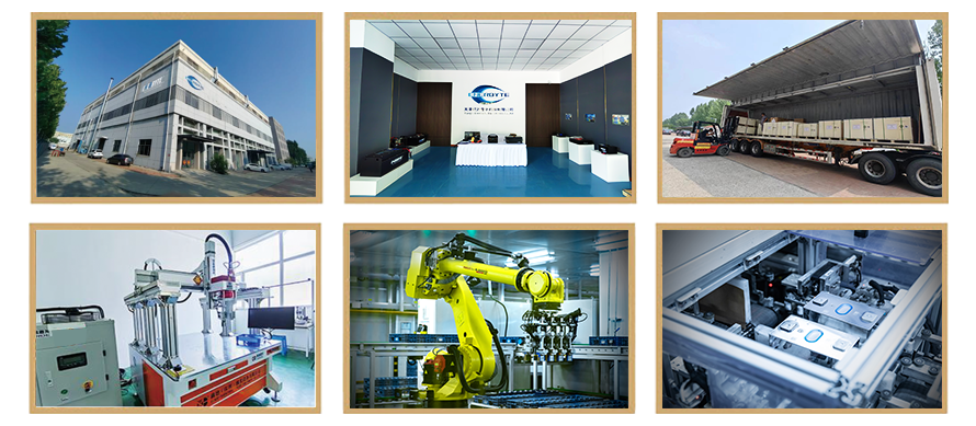
Lithium Batteries ,Ensure Quality
Our lithium battery production line has a complete and scientific quality management system
Ensure the product quality of lithium batteries
Years of experience in producing lithium batteries
Focus on the production of lithium batteries
WE PROMISE TO MAKE EVERY LITHIUM BATTERY WELL
We have a comprehensive explanation of lithium batteries
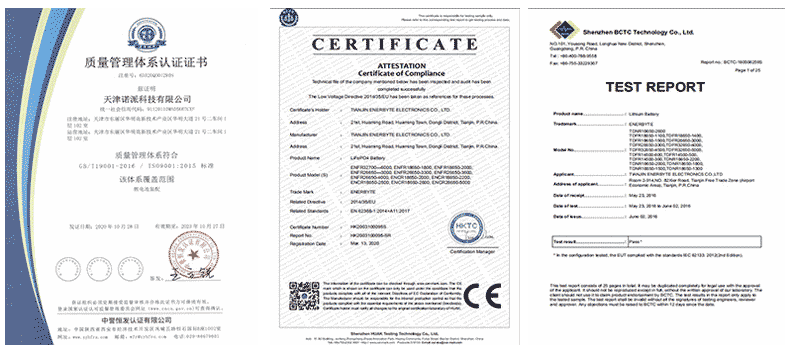
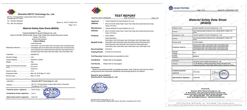
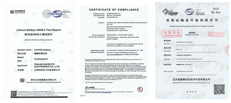
QUALIFICATION CERTIFICATE
THE QUALITY OF COMPLIANCE PROVIDES GUARANTEE FOR CUSTOMERS
MULTIPLE QUALIFICATION CERTIFICATES TO ENSURE STABLE PRODUCT QUALITY
Providing customers with professional and assured products is the guarantee of our continuous progress.

Applicable brands of our products


 Service hotline