24-hour hotline:+8613662168047
Keyword search: battery plant , lithium battery factory , power bank works , lifepo4 battery mill , Pallet Trucks LiFePO4 Battery, LiFePO4 Pallet Trucks Battery, Lithium Pallet Trucks Battery,
As an energy storage device comparable to batteries, supercapacitors have the most significant characteristics of high power density, large capacity, fast charging, high current discharge, multiple charging and discharging times (500000 times), safety, and environmental protection. The disadvantages are large volume, low energy density, high self discharge rate, and low single cell voltage resistance. And compared to batteries, like other capacitors, its voltage continuously decreases during the discharge process. Based on the above characteristics, supercapacitors are not suitable as the main energy storage unit, but are widely used in energy recovery systems to improve startup performance.?? There are two ways to charge capacitors: fixed resistance and fixed current. The fixed resistor method is relatively simple, but the power loss on the resistor is relatively large, and charging is slow. It is generally used during pre charging (per charge). Fixed current charging is similar to the charging of lithium batteries, but the charging current can be much larger. According to the characteristics of supercapacitors, one of their main applications is to be connected in parallel with power batteries to provide high current when the load suddenly increases.
When the motor is operating normally, the current is provided by the lithium battery pack, and this rated current is determined by the characteristics of the battery. At the same time, when the system starts, it charges the supercapacitor from the battery through a charging circuit.
When the motor starts or the load suddenly increases, the current required by the motor is several times the rated current. For batteries, suddenly providing a large current will cause a rapid decrease in battery voltage, resulting in the motor's performance not reaching normal levels.
If a supercapacitor is connected in parallel as shown in the above figure, the sudden increase in current can be provided by the capacitor. In this way, the voltage changes at both ends of the battery and the changes in the current flowing out of the battery will be greatly reduced, which not only greatly helps to improve the performance of the motor, but also greatly reduces the impact on the battery life.
The following two pictures show the comparison of battery voltage and current before and after parallel connection of supercapacitors at the battery end during car startup. It can be clearly seen that with supercapacitors, the instantaneous output power of the battery significantly increases.
As a lithium battery, it can provide much smaller instantaneous current compared to lead-acid batteries, so it should be a good choice to use supercapacitors in electric or hybrid vehicles powered by lithium batteries. As for the selected capacity, it needs to be calculated based on the power of the battery and motor, and can only be determined after various tests in various situations. After all, this thing cannot achieve the desired effect with a small capacity, and a large capacity is a waste of money.
The main responsibility of using supercapacitors to effectively provide high-power pulse output is to extend the lifespan of power batteries, making it easier to successfully use batteries with slightly lower output power.
Main text segmentation line
Introduction to Supercapacitors
Supercapacitors are a special type of capacitor developed in recent years specifically for energy storage. They have a farad level super large capacitance, with an energy density hundreds of times higher than traditional electrolytic capacitors, a leakage current nearly a thousand times lower, and a discharge power nearly ten times higher than batteries. They do not require any maintenance or upkeep, and have a lifespan of over ten years. They are an ideal high-power physical secondary power source and have been successfully used as a starting power source for internal combustion engines; Power supply for starting, accelerating, and climbing electric vehicles; The power supply for the opening and closing operation of high-voltage switches and its use in electric drive armored vehicles and large magnetizing equipment.
At present, China has successfully developed and produced such capacitors. Its series of technical indicators are: capacitance: 0.2F-600F, working voltage: 14V-400V, maximum current 400A-2000A.
The vast majority of high-voltage switch (circuit breaker) operating mechanisms in 35KV substations and 10KV switching stations built in China in the 1960s and 1980s are CDX type electromagnetic operating mechanisms. The distribution rooms of these stations are equipped with corresponding DC systems as DC power sources for opening and closing operations, control, and protection. These DC power supply devices mainly consist of capacitive energy storage silicon rectifier opening and closing devices and some DC screens composed of battery packs.
Due to the characteristics of simple structure, low cost, and low maintenance, the capacitive energy storage silicon rectifier opening and closing device was widely used in these terminal stations at that time. However, these devices exposed a fatal and intolerable flaw in practical use: poor reliability of accidental opening, due to the limited capacity of the energy storage electrolytic capacitor group used (only a few thousand microfactors) and high leakage current. Limited energy storage and significant leakage after power outages make it impossible to ensure the energy required for accident tripping under any circumstances, resulting in serious accidents. Some users have to replace them with small capacity battery packs in order to ensure the energy of opening. However, aside from the expensive price and limited lifespan of battery packs, it is a headache to only maintain them according to regulations in order to work normally. The battery packs here do not bear the task of closing and are in a standby state for a long time. Some problems (such as poor individual batteries and memory effects) are not found in the closing operation like the DC screen of the battery pack. This requires the staff to actively and regularly maintain the batteries. Due to the large workload, it is difficult to fully implement these tasks on site, and some staff even fabricate work records to deceive them. Passed the level, Therefore, it is difficult to ensure whether the internal state of the battery pack is always normal, such as replacing faulty batteries in a timely manner, and periodically eliminating the memory effect of cadmium nickel batteries. Once there is an accident in the power supply line that requires quick opening, it may not provide enough energy and may cause even greater accidents. These phenomena have occurred more than once on some websites, especially on user sites in large industries.
A DC screen composed of batteries can store a large amount of electrical energy and achieve long-term DC supply after a power outage. This is a necessary function in some important stations (such as 110KV and above substations). However, some unimportant terminal stations and user stations do not actually require long-term DC supply after a power outage. Considering the need to ensure the reliability of accident opening, such equipment was used, but it brought about high operating costs. Regular maintenance and short service life. In addition, the failure rate also increases due to the multiple series connections of its batteries (any problem with one battery will affect the normal operation of the entire battery pack).
People urgently hope to find a better solution to the problem of unsatisfactory equipment mentioned above, and the emergence of supercapacitors and their excellent performance bring hope for solving this problem.
One of the application solutions for supercapacitors
This scheme is applicable to the in use capacitor energy storage (or replaced battery pack) type silicon rectifier opening and closing device. The circuit principle modified on the original circuit is shown in Figure 1: the circuit diagram contained in the dashed box in the figure with a cross in the upper right corner represents the electrolytic capacitor group or battery group to be removed during the modification. The circuit diagram contained in the dashed box in the figure is marked with a check mark in the upper right corner, indicating the supercapacitors and circuits to be added. Each supercapacitor has a parameter of 0.85F/280V (850000 microf), and the two supercapacitors operate simultaneously and are hot standby to each other. R1R2 is a charging current limiting resistor. Depending on the required charging speed, 500W or 1000W tungsten halogen lamps (or 100W~200W incandescent lamps) can be selected. The cold state resistance is 5-6 times smaller than the hot state resistance, which is more suitable for reducing the current limiting resistance after the capacitor voltage is established. The advantages of this plan are:
1. While retaining the characteristics of simple structure, low cost, and low maintenance of the original equipment, the absolute reliability of the energy supply for opening is ensured. This is because the energy storage of supercapacitors is several hundred times larger than that of the original electrolytic capacitor group, which can ensure hundreds of opening times after a power outage, with a very large safety margin.
2. The extremely small leakage makes its charge retention ability very strong, and it should have over a hundred opening capabilities after a power outage.
Once one of the capacitors has a problem, it will not affect the independent operation of the other capacitor. Its inspection function can detect a faulty supercapacitor during routine inspections and replace it without affecting the normal operation of the other capacitor.
Application Plan II for Supercapacitors
This plan is mainly applicable to the modified capacitor energy storage type opening and closing device in the production plant. This plan is to replace the high-power closing rectifier power supply of the original capacitive energy storage type opening and closing device with a low-power power supply, which is only used for charging supercapacitors and some frequent loads. The voltage compensation electrolytic capacitor group in the original installation is removed, and the supercapacitor is responsible for the closing of the high-voltage switch and emergency power loss opening. Here, the closing voltage only decreases by about 3V, and this voltage drop will be quickly replenished by charging, making it suitable for continuous closing. The cost of this scheme will be lower than that of the original capacitive energy storage silicon rectifier opening and closing device, and it has the same advantages as Scheme I. It can also provide frequent load power supply for several minutes after a power outage, which is an improvement compared to the original device. The selection of C1, C2, R1, and R2 is the same as Scheme 1. L. The function of R is to only allow frequent load current to pass through and suppress the passing of closing impulse current.
Application Plan Three for Supercapacitors
This plan is applicable to the renovation of DC screens composed of battery packs used in unimportant terminal stations (which do not require long-term DC power supply after power outage). The crossed part in the upper right corner of the circuit diagram contained in the dashed box in the figure is the part to be removed from the renovation. The part marked in the upper right corner of the circuit diagram within the dashed box in the figure is the part to be added for renovation. The function of this scheme is the same as Scheme 2. Due to the elimination of the battery pack, the usage cost is greatly reduced, the maintenance protection amount is reduced, and the power supply life is extended. At the same time, due to the fast charging of capacitors, unlike battery packs, there is a fear of power loss after power outage and opening. The selection of R1R2 is the same as scheme one.
Application Plan Four for Supercapacitors
This plan is to design a new type of DC screen. We know that the selection of battery capacity must meet two conditions simultaneously: the first is to meet the maximum discharge current closing requirement of the impact load. The second requirement is to meet the time requirement under the current of the regular load: when the battery capacity (ampere hours) selected based on the maximum current of the impact load is greater than the capacity requirement of the regular load, the supercapacitor can be combined with the battery pack to form a composite power supply. The supercapacitor bears the impact load, and the battery pack bears the regular load. The capacity of the battery pack is selected to be smaller according to the requirements of the regular load, which not only reduces costs and maintenance, but also protects the battery pack from the impact of high currents and extends its service life. The principle of this composite power supply is shown in Figure 4: the functions of L and R are the same as Scheme 2, and the selection of R1 is the same as Scheme 1.
In addition, cadmium nickel batteries with (ultra) high rate discharge capacity can also be replaced with maintenance free lead-acid batteries of the same capacity, and combined with supercapacitors to form a composite power supply according to Figure 4. This not only retains the small size of the battery, but also significantly reduces the cost of the battery, achieving the same efficiency as using cadmium nickel batteries.
The application of supercapacitors in tax control computers and tax payment machines
The tax department promotes the use of tax control devices and uses international advanced monitoring methods to block invoice loopholes, which is equivalent to installing a "black box" similar to an airplane on each tax control device, which can store recent business information and * * * situations of enterprises. As a result, a series of tax control products have emerged, such as tax control cash registers and IC card tax control refueling machines.
This type of tax control device should have a power outage protection function, which means that in the event of a sudden power outage, it can still store data and perform short-term IC card reading and writing operations. In this case, a backup power supply is needed for protection. The commonly used method is to use batteries for power supply, but there are some drawbacks, as shown in the table below. Supercapacitors, also known as Farad capacitors, are a new type of energy storage component with characteristics between batteries and ordinary capacitors. They can serve as a reliable backup power source for tax control devices.
When a power outage occurs, the supercapacitor provides energy to the control circuit, and the CPU can execute data storage processes in a short period of time. After reading and writing is completed, the capacitor then provides an instantaneous pulse current (a few A) to eject the IC card.
Application of Supercapacitors in Solar Photovoltaic Products
◆ LED: High brightness light-emitting diode
R1, R2: Limiting resistance
◆ C: Ceramic capacitors
◆ D1: Ordinary diode
◆ K: Controlled switch
The work process is briefly described as follows:
When the daytime light is strong, the photoelectric converter converts the light signal into
The electrical signal charges the supercapacitor through a diode and is controlled by a switch
K is disconnected and the LED is not on; When the light is weak at night, photoelectric conversion
The converter stops charging the supercapacitor, and the controlled switch K is conducting
The level capacitor begins to discharge towards the LED until the photoelectric converter returns
Work.
Calculation method for charging and discharging time of supercapacitors
When commonly used on solar indicator lights, LEDs are flashing
For example, using an LED and controlling the flashing discharge duration of 0.05 seconds per second, the charging current of the supercapacitor is 100mA, and the LED discharge current is 15mA
Taking the application of 2.5V50F on solar traffic lights as an example, the charging time of the supercapacitor is calculated as follows:
C×dv=I×t
C: Rated capacity of capacitors;
V: Operating voltage of capacitors;
I: Capacitor charging;
t: Capacitor charging time
Therefore, the charging time of a 2.5V50F supercapacitor is:
t=(C×dv)/I
=(50×2.5)/0.1
=1250s
The discharge time of the supercapacitor is:
C×dv-I×C×R=I×t
C: Rated capacity of capacitors;
V: Operating voltage of capacitors;
I: Capacitor discharge current;
t: Discharge time of capacitors;
R: Internal resistance of capacitors
The discharge time for a 2.5V50F supercapacitor from 2.5V to 0.9V is:
t=C×(dv/I-R)
=50×[(2.5-0.9)/0.015-0.02]
=5332s
Applied to LED, the working time is 5332/0.05=106640s=29.62 hours

Lithium Batteries ,Ensure Quality
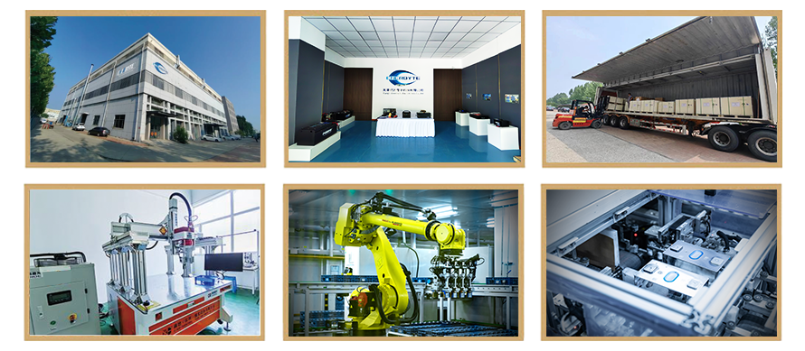
Our lithium battery production line has a complete and scientific quality management system
Ensure the product quality of lithium batteries
Years of experience in producing lithium batteries
Focus on the production of lithium batteries
WE PROMISE TO MAKE EVERY LITHIUM BATTERY WELL
We have a comprehensive explanation of lithium batteries
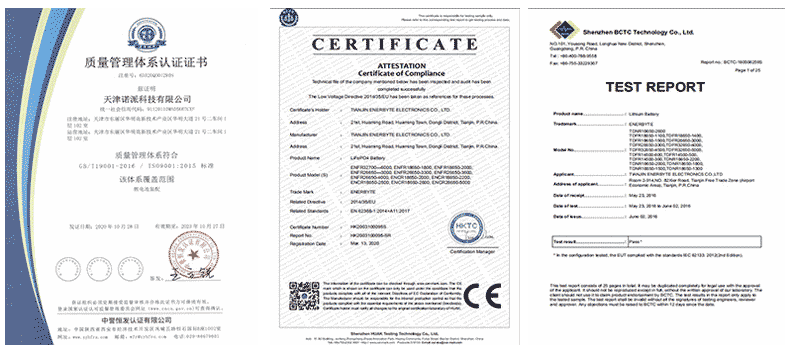
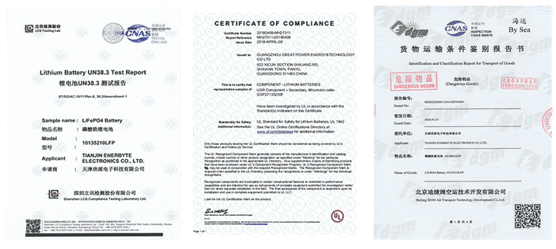
QUALIFICATION CERTIFICATE
THE QUALITY OF COMPLIANCE PROVIDES GUARANTEE FOR CUSTOMERS
MULTIPLE QUALIFICATION CERTIFICATES TO ENSURE STABLE PRODUCT QUALITY
Providing customers with professional and assured products is the guarantee of our continuous progress.


Applicable brands of our products


 Service hotline