24-hour hotline:+8613662168047
Keyword search: battery plant , lithium battery factory , power bank works , lifepo4 battery mill , Pallet Trucks LiFePO4 Battery, LiFePO4 Pallet Trucks Battery, Lithium Pallet Trucks Battery,
1. Single lithium battery protection circuit
There are many specific composition schemes for the charging and discharging protection circuit of a single lithium battery, but the working principles are not significantly different. The following is an analysis of a commonly used circuit in mobile phones for reference.
The control chip of this circuit is DW01 (or 312F), and the MOS switch tube is 8205A, as shown in Figure 6. B+and B - are the positive and negative terminals of the battery cell, respectively; P+and P - are the positive and negative outputs of the protection board, respectively; T is the temperature resistance (NTC) port, which generally needs to be coordinated with the CPU of the appliance to perform protection control.
DWO1 or 312F is a lithium battery protection chip with a high-precision voltage detection and time delay circuit built-in. The main parameters are as follows: overcharge detection voltage is 3V, overcharge release voltage is 4.05V; The overvoltage detection voltage is 2.5V, and the overvoltage release voltage is 3.0V; The overcurrent detection voltage is 5V, and the short-circuit current detection voltage is 1.0V; The maximum current allowed for battery output in DW01 is 3.3A. The pin functions of this chip are shown in Table 1.
Principle diagram of 3.7V lithium battery protection board
(1) Normal operation
The circuit of the protection board is shown in Figure 7. When the voltage of the battery cell is between 2.5V and 4.3V, both pins ① and ③ of DW01 output a high level (equal to the power supply voltage), and the voltage of pin ② is 0V. At this time, both N-channel field-effect transistors Q1 and Q2 inside 8205A are in a conducting state. Due to the small conducting resistance of 8205A, it is equivalent to a direct connection between the D and S poles. At this time, the negative pole of the battery cell is directly connected to the P-terminal of the protection circuit, and the protection circuit has a voltage output. The current circuit is as follows: B+→ P+→ load. P - → pins ② and ③ of 8205A → pins ① of 8205A → pins ⑧ of 8205A → pins ⑥ and ⑦ of 8205A → pins B -.
Principle diagram of 3.7V lithium battery protection board
【 Tip 】 In this circuit, the internal field-effect transistors Q1 and Q2 of 8205A can be equivalent to two switches. When the G-pole voltage of Q1 or Q2 is greater than 1V, the switch transistor conducts, and the internal resistance between D and S is very small (tens of milliohms), which is equivalent to the switch being closed; When the voltage at the G pole is less than 0.7V, the switching tube cuts off, and the internal resistance between the D and S poles is very high (a few megaohms), which is equivalent to the switch being disconnected.
(2) Overdischarge protection
When the battery cell is discharged through an external load, the voltage at both ends of the battery cell will slowly decrease. At the same time, DW01 will monitor the battery cell voltage in real time through resistor R1. When the battery cell voltage drops to 2.3V (usually referred to as the over discharge protection voltage), DWO1 believes that the battery cell is in an over discharge state, and its ① pin voltage changes to Q1 cut-off within 08205A. At this time, the B - and - of the battery cell are in a disconnected state, that is, the discharge circuit of the battery cell is cut off, and the battery cell will stop discharging.
After entering the over discharge protection state, the voltage of the battery cell will rise. If it can rise to the threshold voltage of the IC (usually 3.1V, commonly referred to as the over discharge protection recovery voltage), the ① pin of DW0 will restore the output high level, and Q1 within 8205A will conduct again.
(3) Battery charging
Regardless of whether the protection circuit has entered an over discharge state, as long as a charging voltage is applied between the P+and P - terminals of the protection circuit, DW0 immediately outputs a high level from pin ③ when the charging voltage is detected at the B end. Q2 in 8205A conducts, that is, the P - of the B - protection circuit of the battery cell is turned on. The charger charges the battery cell, and the current circuit is as follows: charger positive pole → p+→ B+→ B+→ B -, 8205A pins ⑥ and ⑦ → 8205A pin ⑧ → 8205A pin ① → 8205A pin ② and ③ → P - → charger negative pole.
(4) Overcharge protection
When charging, when the battery is charged normally through the charger, as the charging time increases, the voltage at both ends of the battery cell will gradually increase. When the voltage of the battery cell rises to 4.4V (usually referred to as overcharge protection voltage), DW01 will determine that the battery cell is in an overcharged state, and even if the voltage of pin ③ drops to 0V, Q2 within 8205A will be cut off due to the low level of pin ④. At this time, the B pole of the battery cell and the P-terminal of the protection circuit are disconnected and maintained, that is, the charging circuit of the battery cell is cut off and charging stops.
When the P+and P - terminals of the protection circuit are connected to the discharge load, although Q2 is cut off, the positive direction of the internal diode is the same as the current direction of the discharge circuit, so it can still discharge the load. When the voltage at both ends of the battery cell is below 4.3V (usually referred to as overcharge protection recovery voltage), DW01 will exit the overcharge protection state, pin ③ will output a high level again, Q2 will conduct, that is, the B-terminal of the battery cell and the P-terminal of the protection circuit will be reconnected, and the battery cell can resume normal charging and discharging.
(5) Overcurrent protection
Due to the presence of internal resistance when the MOs switch tube is saturated and conducting, a voltage drop will occur between the D and S poles of the MOs switch tube when current flows through. The protection and control IC will detect the voltage of the D and S poles of the MOs switch tube in real time. When the voltage reaches the IC protection threshold value (usually 0.15V, referred to as the discharge overcurrent detection voltage), the discharge protection execution end will immediately output a low level, and the discharge control MOs switch tube will turn off, causing the discharge circuit to be disconnected.
In Figure 7, DW01 detects the voltage drop on the MOs switching tube in real time through a resistor R2 connected between the V-terminal and the VSS terminal. When the load current increases, the voltage drop on Q1 or Q2 also inevitably increases. When the voltage drop reaches 0.2V, DWO1 determines that the load current has reached the limit value. Therefore, the voltage of its ① pin drops to 0V, and the discharge control tube Q1 inside 8205A closes, cutting off the discharge circuit of the battery cell. Implement overcurrent protection.
(6) Over temperature protection
The T port on the protection board is the over temperature protection end, connected to the CPU of the electrical appliance. The common over temperature protection circuit is relatively simple, which is to connect an NTC resistor (see R4 in Figure 7) at the T-end and P-end, and install the resistor tightly against the battery cell. When an electrical appliance is in a high-power working state for a long time (such as a phone being in a call state for a long time), the temperature of the battery cell will rise, and the NTC resistance value will gradually decrease. The CPU of the electrical appliance detects the NTC resistance value. When the resistance value drops to the CPU set threshold, the CPU immediately sends a shutdown command to stop the battery from supplying power, only maintaining a small standby current, in order to protect the battery.
【 Tip 】 When the protection board is in a protected state, the B - and P-terminals can be short circuited to activate the protection board. At this time, the charging and discharging protection execution terminals (OC, OD) of the control chip will output a high level, allowing the MOs switch to conduct.

Lithium Batteries ,Ensure Quality
Our lithium battery production line has a complete and scientific quality management system
Ensure the product quality of lithium batteries

Years of experience in producing lithium batteries
Focus on the production of lithium batteries
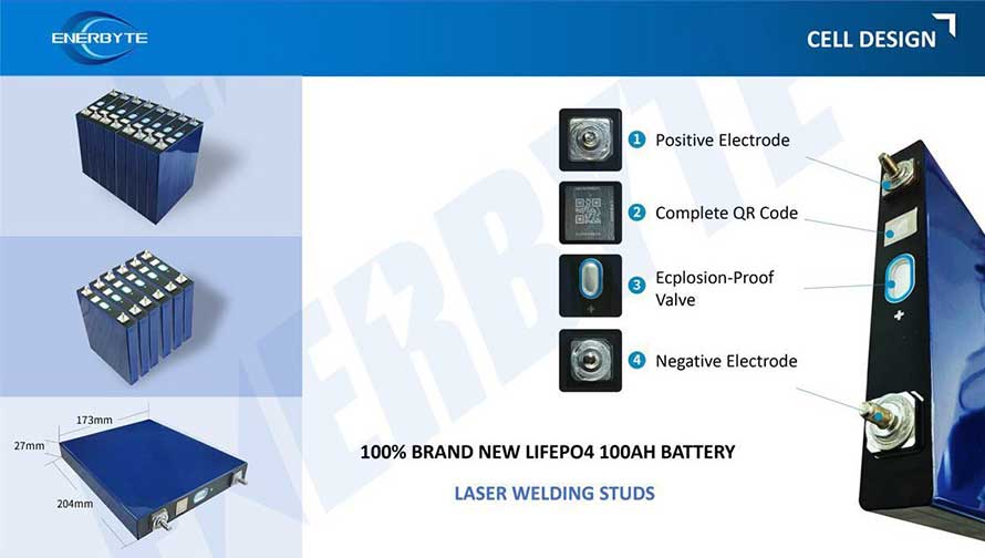
WE PROMISE TO MAKE EVERY LITHIUM BATTERY WELL
We have a comprehensive explanation of lithium batteries
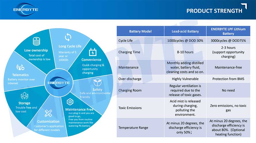
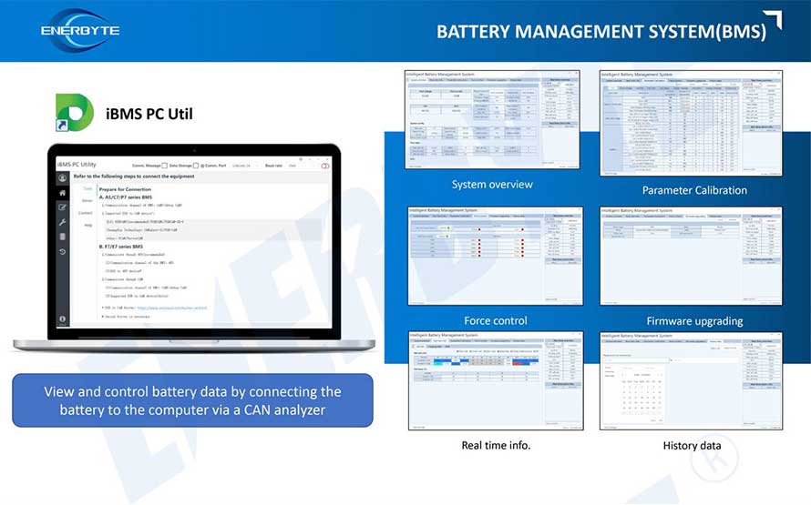
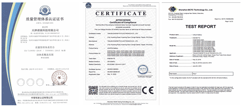
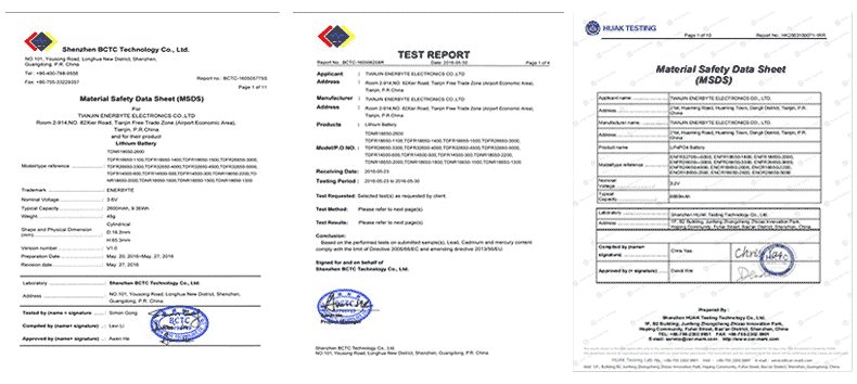
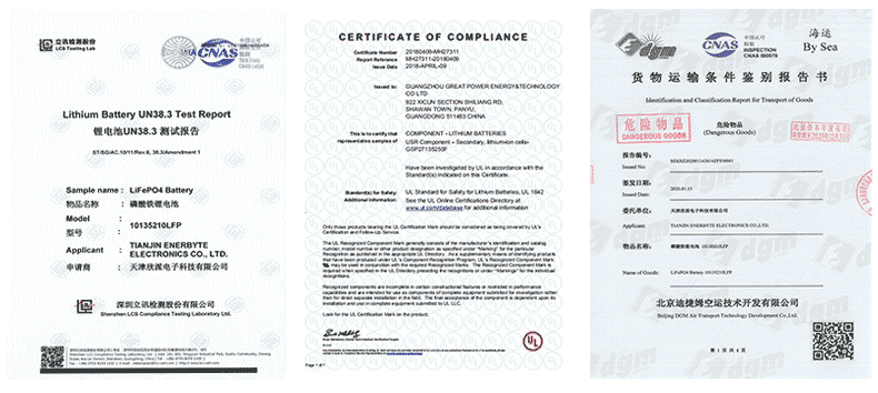
QUALIFICATION CERTIFICATE
THE QUALITY OF COMPLIANCE PROVIDES GUARANTEE FOR CUSTOMERS
MULTIPLE QUALIFICATION CERTIFICATES TO ENSURE STABLE PRODUCT QUALITY
Providing customers with professional and assured products is the guarantee of our continuous progress.

Applicable brands of our products


 Service hotline